


 237 / 306

BONDED
ABRASIVES
237
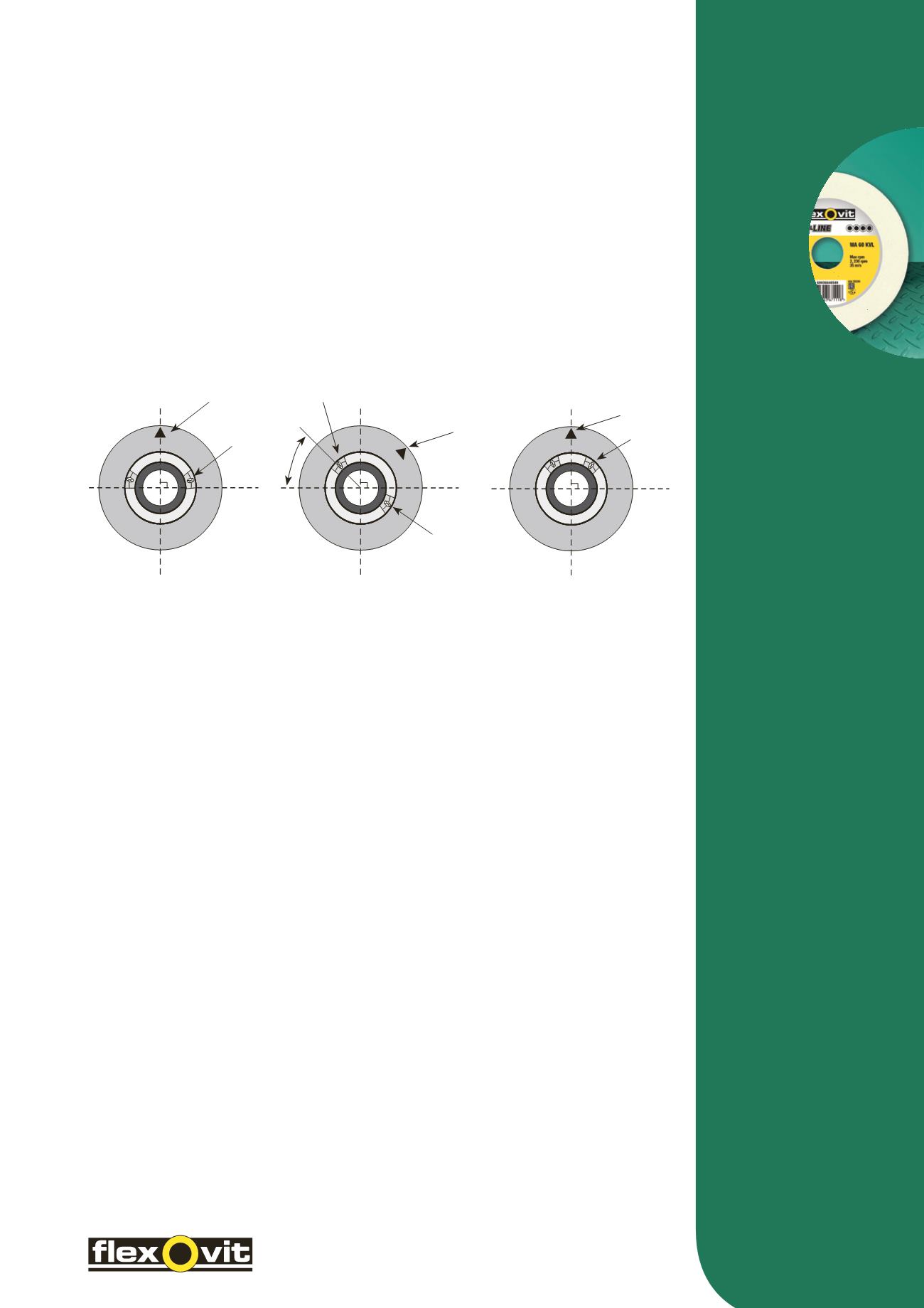
• Mount wheel between flange plates
• Remove balance weights from annular groove on mounting flange (can also be set diametrically opposite
if preferred – ensuring the weights cancel each other out)
• Dress periphery of wheel until running in perfect truth
• Remove complete wheel assembly from the machine (after allowing sufficient time for the coolant to spin out)
and fix assembly onto the balancing mandrel
• Place on balancing unit and allow to turn freely – When stationary mark top centre
(light spot) with chalk
• Re-position the balance weights so that the bottom side face of each weight, that is furthest from the light spot,
forms a right angle i.e. 90°. See illustration 1A
• Turn wheel assembly so that one balance weight is approximately 45 degrees from the horizontal line
and release the wheel. Note the direction in which wheel rotates, the weight may revolve upwards towards
the vertical line. In this instance the weight should be moved down away from the light spot (always adjust
the weights in the opposite direction of rotation) to begin bringing the wheel into balance. See illustration 1B
• Continue checking the weights, alternating between the left and right hand balance weights in turn.
Repeat until the wheel remains stationary in all positions. Move the weights a maximum of 3mm at a time,
reducing this amount as the wheel rotates slower. See illustration 1C
• Continue until assembly remains static in all positions. Lock balancing weights in position and remount
assembly onto the machine spindle
•
Important:
– Ensure the balancing ways (knife edges or rollers) on the balancing stand are level
in all directions. Care must be taken to initially find the true light spot of the wheel.
WHEEL BALANCE
Most Flexovit grinding wheels are balance corrected to a minimum of ISO Standards. Precision grinding machines
usually provide methods of accurately balancing the complete wheel and flange assembly. Modern production
machines are now supplied with automatic balancing systems, whereas, tool-room and older production
machines still have to be manually balanced, ensuring the best possible grinding performance from the wheel.
The balancing procedure can be carried out either on a special balancing stand or in-situ on the machine.
The machine manufacturer’s instructions should be closely followed. There are many methods of manually
balancing the wheel assembly, depending upon the number of balance weights in the wheel arbour, a typical
‘two weight’ balancing system technique is described below.
TWO WEIGHT SYSTEMS
Fig. 1A
Fig. 1B
Fig. 1C
Vertical Line
Vertical Line
Vertical Line
Light Spot
Light Spot
Light Spot
Balance
Weight
Balance
Weight
Balance
Weight